LASER stands for Light Amplification by Stimulated Emission of Radiation. It is one of the outstanding inventions of 20th century. The theoretical basis for the development of laser was provided by Albert Einstein in 1916, when he predicted the possibility of stimulated emission. Charles Townes and his coworkers put Einstein’s prediction for practical realization in 1954 and developed microwave amplifier based on stimulated emission of radiation. It was called a MASER. Shortly thereafter in 1960, the first laser device was developed by T.H. Mainmann by extending the principle of the maser to light.
Interaction of Radiation with Matter:
According to Einstein interaction of radiation with matter could be expressed in term so 3 basic processes:
- Induced Absorption
- Spontaneous emission
- Stimulated emission
1. Induced Absorption: Let E1 and E2 are the energies and N1 and N2 are the number of atoms per unit volume of ground and excited states and ρ(ʋ) be the incident photon density.
If a photon of energy E2 – E1 = hʋ interacts with an atom present in the ground state, the atom gets excited form the ground state to excited state by absorbing the photon energy.
Atom + Photon → Atom*
where * represents the excited state.
So, the process of excitation of an atom from ground state to the excited state by absorbing an incident photon is called Induced Absorption or Absorption.
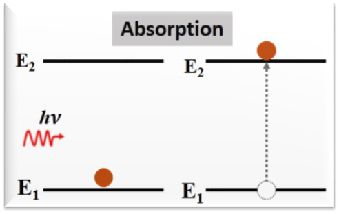
Absorption rate depends upon the number of atoms available in the lowest energy state (N1) as well as the energy density photons 𝜌(ʋ).
Absorption Rate ∝ 𝜌(ʋ) N1
Absorption Rate = B12 𝜌(ʋ) N1
where B12 is known as Einstein coefficient of absorption.
2. Spontaneous emission: The excited atom does not stay in a long time in the excited state and after 10-8 s it comes back to lower energy state by releasing a photon of energy hv = E2 – E1.
Atom* → Atom + Photon
This emission of photon occurs on its own i.e. without any external agent. Hence, it is called spontaneous emission.
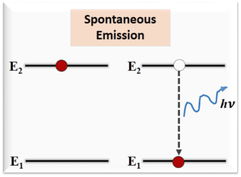
The process of de-excitation of atom from excited state to lower energy state by itself after 10-8s by emitting a photon is known as spontaneous emission.
Spontaneous emission rate depends only on the number of atoms in the excited state.
spontaneous emission rate = A21 N2
where A21 is known as Einstein coefficient of spontaneous emission.
3. Stimulated emission
This process requires the presence of an additional radiation (photon). When an atom in the excited state interacts with an external photon of energy hv = E2 – E1 , this photon triggers or stimulates the excited atom to fall to lower energy state well before the atom can make spontaneous transition.
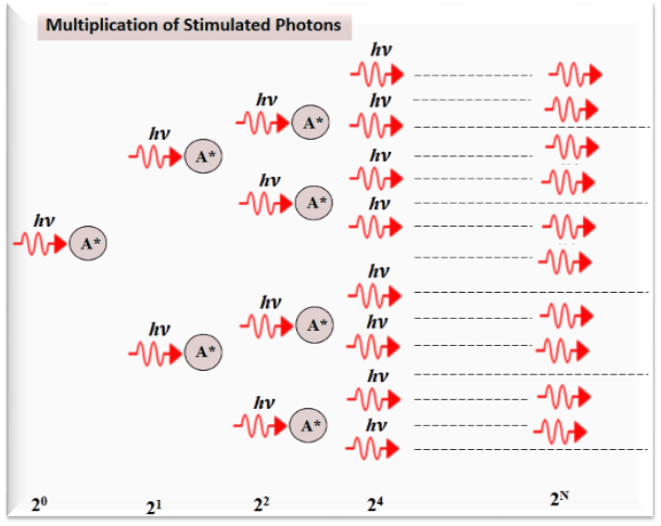
Atom* + Photon → Atom + 2 Photons
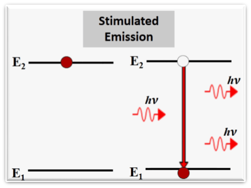
The phenomenon of forced emission of photon by an excited atom due to action of an external agent is called stimulated emission. The photon thus emitted is called stimulated photon.
Stimulated emission depends on N2 i.e.number of atoms available in the excited state as well as the energy density of photons ρ(ʋ).
Thus, Stimulated emission rate ∝ N2 ρ(ʋ)
or, Stimulated emission rate = B21 N2 ρ (ʋ)
where B21 is known as Einstein coefficient of stimulated emission.
Comparison: Spontaneous and Stimulated Emission
| Spontaneous emission | Stimulated emission | |
| 1. | The spontaneous emission was postulated by Bohr. | The stimulated emission was postulated by Einstein |
| 2. | It is a random process. | It is not a random process. |
| 3. | Additional photons are not required in spontaneous emission. | Additional photons are required in stimulated emission. |
| 4. | One photon is emitted in spontaneous emission. | Two photons are emitted in stimulated emission. |
| 5. | The photons are emitted uniformly in all directions. As a result, light is non-directional. | Photons emitted in this process travel in same direction as that of stimulating photon. As a result, light is produced is highly directional. |
| 6. | The emitted radiation is Incoherent. | The photons emitted in this process are all in phase. Hence, emitted radiation is coherent. |
| 7. | The emitted radiation is less intense. | The emitted radiation is high intense. |
| 8. | Emitted radiation is not monochromatic. | The emitted radiation is nearly monochromatic. |
| Example: light from sodium or mercury lamp. | Example: light from laser source. |
Einstein Coefficients & their Relations:
It establishes the relation between the three coefficients i.e. stimulated absorption (B12), spontaneous emission (A21) and stimulated emission (B21) coefficients.
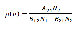
In thermal equilibrium the mean population N1and N2 in lower (E1) and upper energy levels (E2) must remain constant. This is possible only if the upward transitions and downward transitions i.e.
no. of atoms absorbing photons/sec/vol. = no. of atoms emitting photons/sec/vol. ……..(1)
The no. of atoms absorbing photons/sec/vol. = B12 N1 ρ(ʋ)
where r(u) energy density photons and B12 is the Einstein coefficient of stimulated absorption.
The no. of atoms emitting photons/sec/vol. = A21 N2 + B21 N2 ρ(ʋ)
where A21 is the Einstein coefficient of spontaneous emission and
B21 is the Einstein coefficient of stimulated emission.
If the system is in equilibrium the upward transitions must be equal downward transitions.
𝐵12𝑁1𝜌(𝜐) = 𝐴21𝑁2 + 𝐵21𝑁2𝜌(𝜐)
𝐵12𝑁1𝜌(𝜐) − 𝐵21𝑁2𝜌(𝜐) = 𝐴21𝑁2
𝜌(𝜐)(𝐵12𝑁1 − 𝐵21𝑁2) = 𝐴21𝑁2
Divide with 𝐵21𝑁2 in numerator and denominator in R.H.S of the above equation
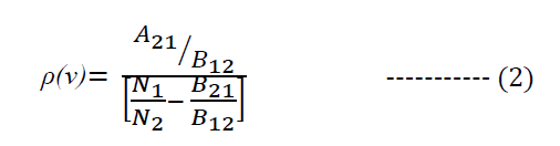
But,
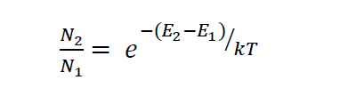
k is the Boltzmann’s constant and T the absolute temperature.
As, E2 – E1 = h𝜐
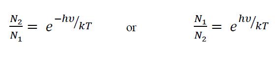
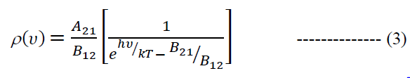
Therefore, equation (2) becomes
In order to maintain thermal equilibrium, system must release energy in the form of em radiation.
According to Planck’s law
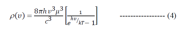
where μ is refractive index of the medium and c is the velocity of light in free space.
Equations (3) and (4) will be consistent only if
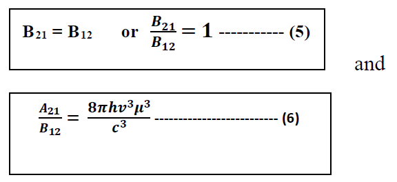
The above relations (5) and (6) are known as Einstein coefficients relations. These coefficients are related through
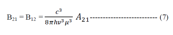
- Relation (5) shows that the coefficients for both absorption and stimulated emission are numerically equal. this equality implies that when an atom with two energy levels is placed in a radiation field, the probability for an upward transition (absorption) is equal to the probability for an downward (Stimulated) transition.
- Relation (6) shows that the ratio of coefficients of spontaneous vs. stimulated emissions is proportional to the cube of frequency of radiation. That’s why it is somehow difficult to achieve laser action in higher frequency ranges such as X-rays.
- Condition for Stimulated Emission to Dominate Spontaneous Emission
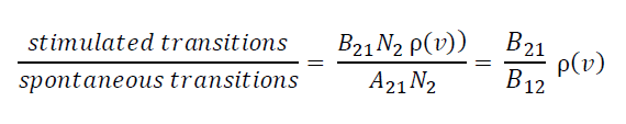
From above relation it is clear that the stimulated emissions>> spontaneous emission only if the radiation density is very large. Thus, presence of large number of photons in active medium is required.
However, it will lead increased absorption rates.
- Condition for Stimulated Emission to Dominate Absorption Transitions
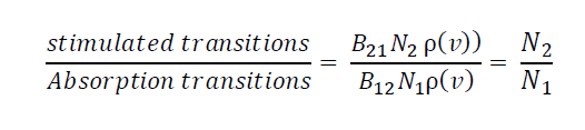
Stimulated transitions >> Absorption process, only when
N2 > N1, i.e. there should be more number of atoms in the higher energy level than in the lower energy level.
Population Inversion:
POPULATION: Number of atoms per unit volume (N) that occupy a particular energy state is referred as the population of that energy level.
Population of an energy state depends on the temperature T, according to Boltzmann’s Equation
N = No e-E/kT
Here No is the population in the ground state (E = 0), k is the Boltzmann’s constant and T the absolute temperature.
At thermal equilibrium, population is maximum in the ground state and decreases exponentially as one goes to higher energy states. If N1 and N2 are the populations in two states, a lower state E1 and a higher state E2 we have:
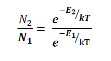

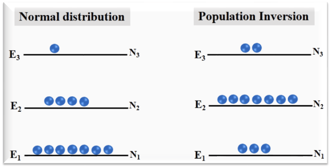
clearly, N2 < N1 since E2 > E1.
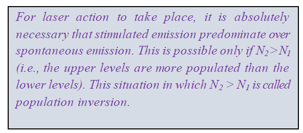
The state in which the number of atoms present in the excited state (N2) is greater than the number of atoms present in the ground state (N1) i.e. (N2 >> N1) is called population inversion.

Pumping & Pumping Mechanisms:
For achieving and maintaining a state of population inversion atoms have to be raised continuously to excited state. It requires energy to be supplied to the system.
The process of supplying energy to the medium with a view to transfer it into state of population inversion is known as pumping.
Commonly used pumping methods are : —
- Optical pumping: Light source or flash discharge tube is used to raise the atoms to higher energy states. Optical pumping method is adopted in solid state lasers.
- Chemical pumping: Chemical reactions are used to raise the atoms. Electrical discharge pumping is used in gas lasers.
- Electrical pumping: In this method, an applied electric field causes ionization of the medium and raises them to the excited state. As a result, atoms rise to the higher states. This method is used in gas lasers.
- Direct conversion: In this method the electrical energy directly creates the state of population inversion and laser is produced. This pumping mechanism is used in semiconductor lasers. In Semiconductor diode laser, a direct conversion of electrical energy in to light energy takes place.
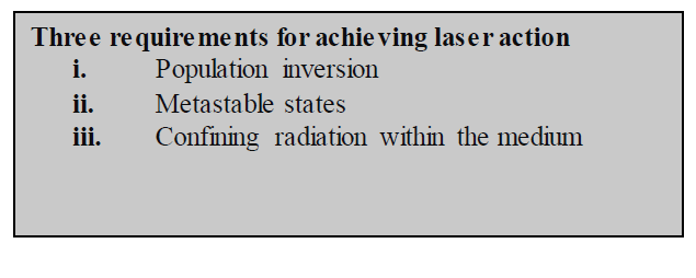
Metastable States:
Normally, excited atoms have short lifetimes and release their energy in a matter of (10-8s) through spontaneous emission. Hence, population inversion cannot be established under such circumstances.
A metastable state is an excited state (intermediate state) of an atom or other system with a longer lifetime than the other excited states. Atoms in the metastable state remain excited for a longer time. The lifetime of a metastable state is in the order of 10-6 to 10-3 s.
- A large number of excited atoms are accumulated in the metastable state.
- The population of metastable state can exceed the population of a lower level thereby establishing population inversion in a lasing medium.
- Population inversion could not be created without a metastable state and hence no laser action is possible.
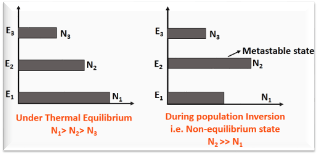
EXTRA Information: Refer to figure above, when a suitable energy is supplied to the system, atoms get excited into E3. After their lifetime the atoms are transit into E2. Due to more lifetime of an atom in state E2 (as it is a metastable state), the atoms stay here for longer time than compared to state E3. Because of the accumulation of atoms in state E2, the state of population inversion is achieved between states E1 and E2.
Components of Laser:
Every LASER consists of three basic components. These are –
- Lasing material or Active Medium.
- The Pump
- Optical resonator.
- Active Medium: The active medium is the material in which lasing action takes place. It is a medium which when excited reaches the state of population inversion and promotes stimulated emissions leading to light amplification.
This medium decides the wavelength of laser radiation. The active medium contain atoms which can produce more stimulated emission than spontaneous emission and cause amplification they are called “Active Centers” and rest of the medium acts as host and supports active centers. This host medium is called active medium.
Semiconductors, gases (He, Ne, CO2, etc), solid materials (YAG, sapphire (ruby) etc.) are usually used as lasing materials and often LASERs are named for the ingredients used as a medium.
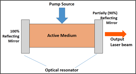
- The Pump: The pump (excitation source) provides energy which is needed for the population inversion and stimulated emission to the system. Pumping can be done in different ways – optical method, electrical discharge method and direct conversions.
Examples of pump sources are electrical discharges, flash lamps, arc lamps, light from another laser, chemical reactions etc.
- Optical Resonator: The active medium is enclosed between a fully reflective mirror and partially reflective mirror. These mirrors constitute the optical cavity or resonator.
The reflectors enhance the stimulated emission process by reflecting the photons into the active medium. As a result we get high-intensity monochromatic and coherent laser light through the partially reflecting portion of the mirror.
Properties of Laser Beam:
Laser radiation has the following important characteristics over ordinary light source. They are:
i) Monochromaticity:
It means that the laser light consists of nearly one color or single wavelength, wheras an ordinary/conventional light is a combination of many different wavelengths (colors). Monochromaticity is the major characteristic of laser making it different from ordinary light sources.
The wavelengths spread of conventional light sources is usually 1 in 106, whereas in case of laser light it will be 1 in 1015.
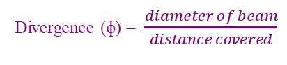
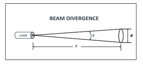
ii) Directionality:
The lasers emit light that is highly directional i.e. it does not diverge or spread out. The laser beam is well collimated, relatively narrow beam in a specific direction i.e. it travels a long distance with very little spread (low divergence).
Whereas ordinary light, e.g. one that coming from the sun, a light bulb, or a candle, is emitted in many directions away from the source.
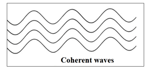
iii) Coherence:
All the emitted photons of laser light have constant phase relationship with each other in time and space. That is the wavelengths of laser light are in phase in space and time.
iv) High Intensity:
The power output of laser beam varies from few milliwatts to few kilowatts. But this energy is concentrated in a beam of very small cross section area, so it has very high intensity. The energy of laser beam is approximately given by:
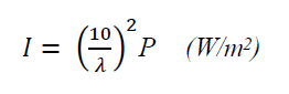
where P is the power radiated by the laser.
Since, laser beam is concentrated in a very small cross section area, so, even 1 Watt laser would appear many thousand times more intense than 100 Watt ordinary lamp. Hence, laser light has greater intensity when compared to the ordinary light.
Example: For a He-Ne laser of 1 mW and wavelength 6328 Å, intensity is calculated as
I = 2.5 X 10¹¹ W/m2
Types of Laser:
LASERs are categorized on various parameters.
- By Active Medium
- Solid State laser
In these type of lasers solid state materials are used as active medium.
Examples: Ruby laser, Nd:YAG laser, Ti:Sapphire laser.
- Gas Laser
In these type of lasers gases are used as the active medium.
Example: He-Ne laser, CO2 laser, Argon-ion laser.
3. Semiconductor Lasers
In these type of lasers, junction diodes are used. The semiconductor material is doped with both the acceptors and donors. These are also known as injection laser diodes. In such diode lasers whenever the current is passed, light can be seen at the output.
Example: GaAs laser, GaN laser, InGaN laser.
- By mode of operation
- Continuous Wave (CW)
- Pulsed mode
- By pumping and laser levels
- 3-level laser
- 4-level laser
Ruby Laser
- Ruby laser is the type of solid state laser.
- It is the first laser invented in 1960.
- It produces visible red light of wavelength 694.3 nm.
- Uses 3-level pumping scheme.
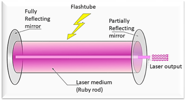
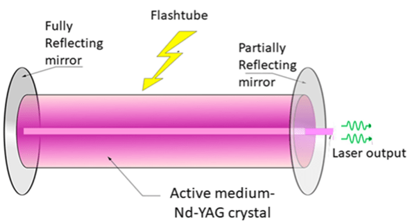
Construction: Ruby laser consists of 3 main parts:
Active medium: Al2O3 crystal containing about 0.05% Cr+3 ions. Cr+3 ions act as active centres.
Pump source: Optical pumping (Xenon flash lamp)
Optical resonator: The ruby rod is placed between two mirrors which are silvered. One mirror is fully silvered whereas, another mirror is partially silvered. The fully silvered mirror will reflect 100% of the light whereas the partially silvered mirror will reflect 90% part of the light and allows approx. 10% of light to pass through it to produce output laser beam.
Ruby laser comprises of ruby rod of approx. 4cm length and 0.5 cm diameter. Both the ends of the rods are highly polished and made strictly parallel. The ends are silvered in such a way, one becomes partially reflected and the other end fully reflected. The ruby rod is surrounded by Xenon flash tube, which acts as a pumping source for exciting the Cr+3 ions to the upper energy levels.
Working of Ruby laser: Ruby laser uses 3-level pumping scheme.
- When the flash lamp is switched on, the Xenon discharge generates an intense burst of white light.
- The chromium ions get excited to the higher energy level (E3). The lifetime of the ions at the energy level E3 is very small (10-8 sec) so the electrons do not stay there for long period.
- After approx.10-8 sec, they fall into the metastable state E2 via non-radiative transitions.
- The lifetime of metastable state E2 is 10-3 sec which is much greater than the lifetime of state E3. So, the Cr+3 ions stay there for a longer time duration.
- Hence, there is an increase in the population of Cr+3 ions in the metastable state E2 and so, the population inversion is achieved.
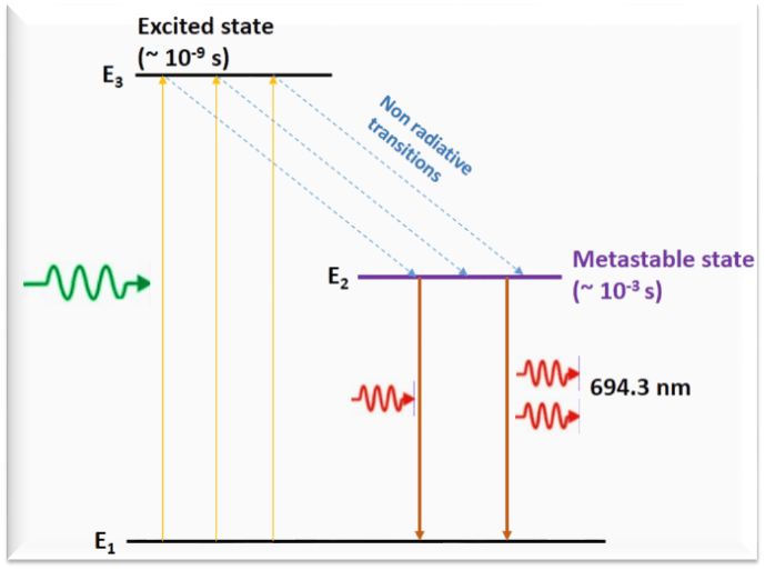
After some period, the Cr+3 ions in the metastable state E2 falls into the lower energy state E1 via spontaneous emission and emit photons.
These photons then initiate a chain of stimulated emissions by triggering the excited ions to fall to ground state E1.
Photons (light) of wavelength 6943Å are produced in the medium. They travel along the axis of the ruby rod and will bounce back and forth between the two end mirrors. Hence, light is amplified and a strong intense beam of red light emerges out of the partially reflecting mirror.
Salient features:
- Uses 3-level pumping scheme.
- Active centres are Cr+3 ions.
- Light from xenon flash tube acts as pumping source.
- Operates in Pulsed mode.
- Has poor efficiency.
Nd:YAG Laser
- Nd: YAG i.e. Neodymium-doped Yttrium Aluminum Garnet laser is a type of solid state laser in which Nd:YAG is used as a laser medium.
- It produces laser beam in the near-IR region at 1064 nm.
Construction
Nd:YAG laser consists of 3 main parts:
- Active Medium: Synthetic crystalline material (Yttrium Aluminum Garnet) (Y3Al5O12) doped with Nd+3 ions, is used as an active medium in Nd:YAG laser. The doping concentration is typically of the order of 0.725% by weight. Nd+3 ions act as active centres.
- Pump source: (Optical pumping) Light energy sources such as Krypton flashtube or laser diodes are used as energy source for supplying energy to the active medium.
- Optical resonator: The Nd:YAG crystal is placed between two mirrors which are silvered. One mirror is fully silvered whereas, another mirror is partially silvered. The fully silvered mirror will reflect 100% of the light whereas the partially silvered mirror will reflect 90% part of the light and allows approx. 10% of light to pass through it to produce output laser beam.
Working of Nd:YAG Laser
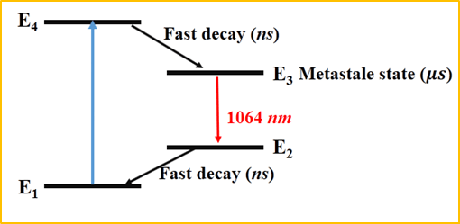
A simplified energy level diagram of Nd:YAG laser is shown in figure below.
- When flashtube or laser diode is switched on, the Nd+3 ions gets excited to the upper energy level E4.
- The lifetime of higher energy state E4 is very small (10-8 sec) so the Nd+3 ions do not stay there for long period and fall to the next lower energy state E3 which is a metastable state by non-radiative transition.
- The lifetime of metastable state E3 is high as compared to the lifetime of state E4. So, population inversion is achieved between states E3 and E2.
- After sometime, the ions in the metastable state E3 will make a spontaneous transition to the energy state E2 by releasing a photons.
- These photons then initiate a chain of stimulated emissions by triggering the excited ions to fall to ground state E1.
- Photons that are produced in the medium, travel back and forth between the two end mirrors. Hence, light is amplified and a strong intense beam of wavelength 1064 nm emerges out of the partially reflecting mirror
- Nd+3 ions return to the Ground state (E1) from E2 by non radiative transitions.
Salient features:
- Uses 4-level pumping scheme.
- Active centres are Nd+3 ions.
- Light from Krypton flash tube or laser diode acts as pumping source.
- Operates in both Pulsed and Continuous wave (CW) mode.
- Its efficiency is high as compared to the ruby laser.
- Low power consumption
He-Ne Laser:
- It is a type of gas laser developed in 1961.
- He-Ne laser was the first continuous wave (CW) laser ever constructed.
- It emits a laser beam of wavelength of 632.8 nm in the red portion of the visible spectrum.
- Main advantage of gas lasers over solid state lasers is that they are less prone to damage by overheating.
Construction:
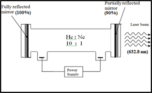
He-Ne laser comprises of 3 main parts:
- Active Medium: In He-Ne gas laser, active medium is made up of a mixture of He and Ne gases taken in the ratio 10:1 in the glass discharge tube at low pressure. Neon atoms are the active centres.
- Pump source: High voltage DC power supply (~10 kV).
- Optical resonator: Two reflecting mirrors are fixed on both the ends of the discharge tube. One mirror is partially reflecting and the other is fully reflecting. This arrangement of mirrors act as optical cavity or Fabry-Perot resonator.
In He-Ne laser discharge tube is generally made up of 80 cm length and 1 cm diameter. The output power of these gas lasers depends on the length of the glass discharge tube and pressure of the gas mixture.
Neon atoms in He-Ne laser are the active centers and have energy levels suitable for laser transitions while helium atoms help in exciting neon atoms.
Working:
- When power is switched on, a high voltage of about 10 kV is applied across the gas mixture. It ionizes the gas.
- The electrons and ions produced in the process of discharge are accelerated towards the anode and cathode respectively. They collide with He and Ne atoms on their way.
- The energetic electrons transfer some of their energy to the He atoms in the gas and excite them to the metastable states (as they are lighter).
- He atoms in the metastable state cannot return to ground state by spontaneous emission. But, they can return to ground state by transferring their energy to neon atoms through collisions.
- The energy levels of some of the excited states of the neon atoms are identical to the energy levels of metastable states of the helium atoms. Therefore, resonant energy transfer occurs between excited He atoms and ground level Ne atoms.
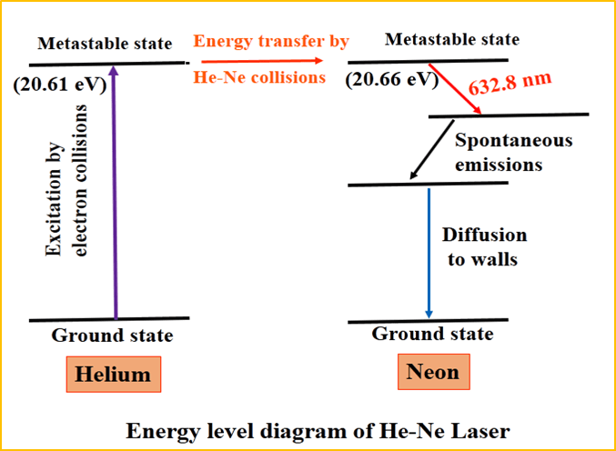
- He atoms drop to ground state after exciting neon atoms. Thus, He atoms help Ne atoms in achieving population inversion.
- This excited state of neon atoms is a metastable state and thus, have longer lifetime. Therefore, a large number of neon atoms will get accumulated in the metastable states and so, population inversion is achieved.
- After sometime, the neon atoms in the metastable states (E4) will spontaneously fall into the next lower energy states (E3) by releasing photons of wavelength 632.8 nm.
- These photons will further trigger a chain of stimulated emissions, which will produce photons of wavelength 632.8 nm.
- These photons will bounce back and forth between the end mirrors, causing more and more stimulated emissions with each passage. Hence, light is amplified and a strong intense laser beam comes out from the partially reflecting mirror.
- The excited neon atoms come to the ground state through frequent collisions with the walls of the glass discharge tube and again available for excitation to higher energy levels and participation in laser action. It is important for the continuous wave (CW) operation.
Salient features
- Uses 4-level pumping scheme.
- Active centres are Neon atoms.
- Electric discharge is the pumping source.
- Operates in Continuous wave (CW) mode.
- Low efficiency and low power output.
Advantages of Helium-Neon laser
- Helium-Neon laser emits laser light in the visible portion of the spectrum.
- It has high stability.
- It is of low cost.
- It operates at higher temperature without any damage.
Disadvantages of Helium-Neon laser
- It gives low efficiency
- Its applications are limited to low power tasks only.
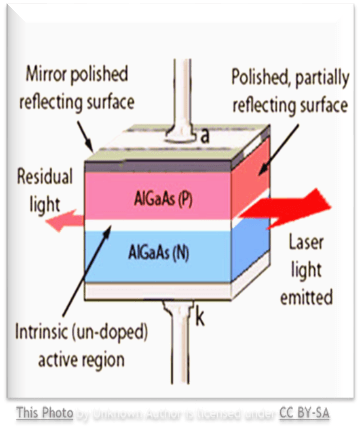
Semiconductor Laser:
- It is a solid state semiconductor laser.
- Gallium Arsenide (GaAs) laser gives IR radiation in the wavelength 8300 to 8500 Å .
- It emits light under forward biasing.
- Emitted light is in near IR region.
- These are also known as laser diodes.
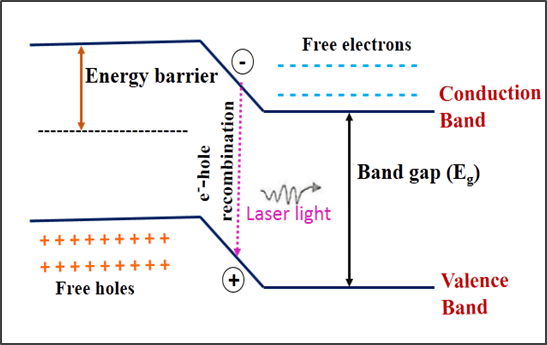
Principle:
When a p-n junction diode is under forward bias, the electrons from n-region and holes from p-region cross the junction. In the process, electrons from the conduction band jumps into a hole in the valence band and excess energy is released in the form of photons.
This electron-hole recombination is the basic mechanism responsible for emission of light in laser diodes.
The wavelength of light emitted is given by the relation:

The photon emitted during recombination process stimulates other electrons and holes to recombine. As a result, stimulated emission takes place. This results in the release of excess number of photons all of which are in exact phase with the initial photons and so the output gets amplified and laser beam is obtained.
Construction:
- Active Medium: A pn junction diode made of single crystal of GaAs is used as an active medium.
- Pump source: The direct conversion method.
- Resonating cavity: The end faces of the junction diode which are well polished and parallel to each other, act as an optical resonator through which the emitted light comes out.
For the fabrication of semiconductor laser diodes direct band gap semiconductors are preferred because they emit energy in the form of light (photons) on recombination of electron and hole pairs. Compound semi-conductor materials such as GaAs, GaP and InP are some of the examples for direct band gap semiconductors.
A typical semiconductor laser consists of following parts:
- Metal Contact
- P-type Material
- Active/Intrinsic Region
- N-type Material
- Metal Contact
Working:
- Heavily doped p and n regions are used in fabrication of laser diodes.
- When the junction is forward biased, electrons and holes are injected into the junction region in high concentrations.
- When diode current reaches a certain threshold value, the carrier concentration in the junction will be very high.
- The junction region will have a large number of electrons in the conduction band and a large amount of holes in the valence band.
- A hole is just an absence of electron. So, upper energy levels will have a high population of electrons whereas the lower energy levels will have absence of electrons.
- Therefore, condition of population inversion is achieved in the narrow junction region. This region is also called active region.
- In the active region, electron-hole pair will recombine and will emit a photon via spontaneous emission.
- This photon will stimulate the electrons in conduction band to valence band causing electron-hole recombination.
- When the forward bias voltage is increased further, more number of photons will be emitted. These photons will trigger a chain of stimulated recombinations resulting in the release of a large number photons all having same phase and amplitude.
- These photons will move back and forth and by reflection between two parallel and opposite sides to each other and will grow in strength.
- After gaining enough strength, laser beam of wavelength 8400Å will emerge out as output.
Salient features:
- Diode lasers are very small in size (0.1 mm long) and are portable.
- have high efficiency around 40%
- Altering the bias voltage laser output can be altered.
- operate at low powers.
Applications of semiconductor laser
1. Optical fibre communication
2. Barcode readers
3. Laser printers
4. CD/DVD reading/recording
5. Medical surgery
6. Diamond cutting
Applications of Lasers:
Lasers in Communications:
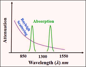
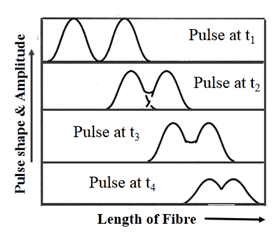
1. Laser light is used in optical fiber communications to send information over large distances with minimum losses.
2. Laser light is used in underwater communication networks.
3. Lasers are used in space communication, radars and satellites etc.
Lasers in Industries:
1. Lasers are used in cutting, welding and drilling.
2. They are used in electronic industries for trimming the components of Integrated Circuits (ICs).
3. Lasers are used for heat treatment purposes in the automotive industry.
4. Lasers are used in bar code scanners.
Lasers in Science and Technology:
1. Lasers are used in computers to get stored information from a Compact Disc (CD).
2. They are used in storing large amount of information or data in CD-ROM.
3. They are used for the measurement of pollutant gases and other contaminants in the atmosphere.
4. Lasers are used in computer printers.